- Commissioning
- Connect devices
- VARTA energy storage
VARTA energy storage
This page describes how to connect a VARTA energy storage system to the SOLARWATT Manager.
Table of contents
Compatibility
| EnergyManager pro | Manager flex | |
|---|---|---|
| pulse neo | ||
| element S5 backup |
Installation and configuration
Number of connectable VARTA: 1
Interface: Ethernet
Interface: Ethernet
Preliminary remarks
- The installation and configuration of the VARTA energy storage system may only be carried out by certified electricians in accordance with the specifications of VARTA AG. Certification training is a prerequisite for installation and warranty.
- VARTA element S5 backup with a serial number < 127101623 require a firmware update.
Contact VARTA Technical Support (+49 9081 240 - 86 6044; technical.service@varta-storage.com) after successful commissioning in accordance with VARTA's certification training and before connecting to the EnergyManager pro and have the firmware update installed. - Simultaneous control of system components (inverters, loads) by the EnergyManager pro and the VARTA energy management system leads to system malfunction. Therefore, only control the system via the EnergyManager pro.
- The use of a VARTA storage system in combination with the SOLARWATT Manager requires the installation of one of the following 2-directional meters in addition to the VARTA Split Core Sensor:
Wiring diagram
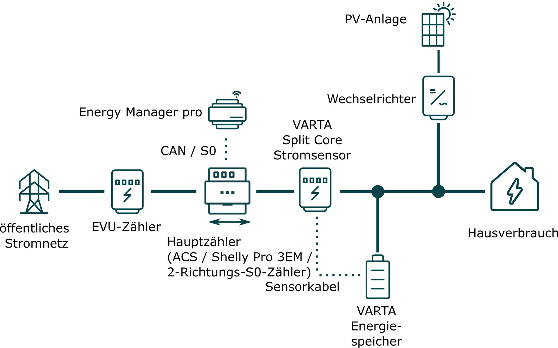
Installation of a SOLARWATT AC-Sensor as main meter
Interface: CAN
- Establish and check the disconnect.
- Install the AC-Sensor on the top-hat rail in the switch cabinet.
- Install the AC-Sensor directly behind the utility meter.
- Install the VARTA Split Core current sensor and the feed points of the VARTA energy storage system and PV system between the house consumption and the main meter on the house side.
- The individual components must be connected in series. Observe the phase equality and the clockwise rotating field.
- Install the VARTA Split Core current sensor on the top-hat rail in the switch cabinet. Follow the Installation instructions from VARTA (mandatory requirement: VARTA certification training).
- Connect the AC-Sensor to the EnergyManager pro via CAN data cable.
- Restore the power supply.
- Connect the VARTA energy storage system to the VARTA Split Core current sensor via the sensor cable (included in the scope of delivery of the VARTA energy storage system).
- Connect the VARTA energy storage system to the customer network via Ethernet (LAN data cable; RJ45 plug).
- Configure the VARTA energy storage system in accordance with the VARTA operating instructions. You will receive the documents at the VARTA certification training course.
- Assign a static IP address to the VARTA Energy Storage System via the router's user interface.
Installation with Shelly Pro 3EM as main meter
Interface: Ethernet / WLAN
Applicable document: Shelly Pro 3 EM
- Establish and check the disconnect.
- Install the Shelly Pro 3EM on the top-hat rail in the switch cabinet. Observe the phase alignment.
- Observe the installation direction of the Shelly Pro 3EM, further information is available here: Shelly Pro 3EM
- Install the VARTA Split Core current sensor on the top-hat rail in the switch cabinet. Follow the Installation instructions from VARTA (mandatory requirement: VARTA certification training).
- Connect the AC-Sensor to the EnergyManager pro via CAN data cable.
- Restore the power supply.
- Connect the VARTA energy storage system to the VARTA Split Core current sensor via the sensor cable (included in the scope of delivery of the VARTA energy storage system).
- Connect the VARTA energy storage system to the customer network via Ethernet (LAN data cable; RJ45 plug).
- Configure the VARTA energy storage system in accordance with the VARTA operating instructions. You will receive the documents at the VARTA certification training course.
- Assign a static IP address to the VARTA Energy Storage System via the router's user interface.
Installation with 2-way S0 meter as main meter
Interface: S0 input
- Establish and check the disconnect.
- Install the 2-directional S0 meter directly behind the EVU meter. Ensure that the phases are in phase.
- connect the 2-direction S0 meter to the EnergyManager pro via the S0 data cable.
Example in the illustration: Connection terminals on the KDK PRO380-S
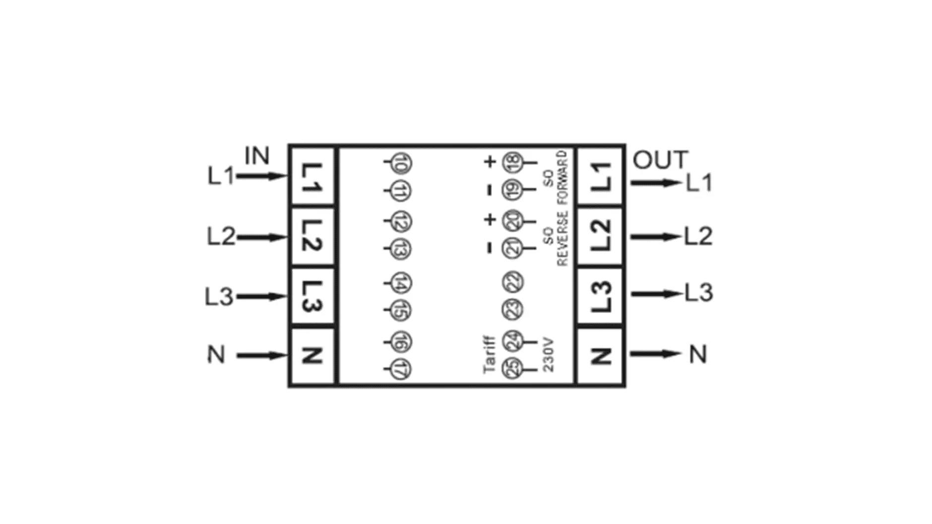
| L1 (in) | Phase 1 input (mains) |
| L1 (out) | Phase 1 output (house) |
| L2 (in) | Phase 2 input (mains) |
| L2 (out) | Phase 2 output (house) |
| L3 (in) | Phase 3 input (mains) |
| L3 (out) | Phase 3 input (house) |
| N (in) | Neutral input (mains) |
| N (out) | Neutral output (house) |
| 18/19 | Pulse output (S0) "Reference" +/- |
| 20/21 | Pulse output (S0) "Supply" +/- |
- Install the VARTA Split Core current sensor on the top-hat rail in the switch cabinet. Follow the Installation instructions from VARTA (mandatory requirement: VARTA certification training).
- Restore the power supply.
- Connect the VARTA energy storage device to the VARTA Split Core current sensor via the sensor cable (included in the scope of delivery of the VARTA energy storage device).
- Connect the VARTA energy storage system to the customer network via Ethernet (LAN data cable; RJ45 plug).
- Configure the VARTA energy storage system in accordance with the VARTA operating instructions. You will receive the documents at the VARTA certification training course.
- Assign a static IP address to the VARTA Energy Storage System via the router's user interface.
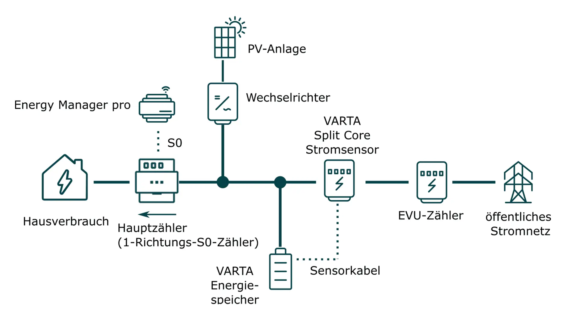
Installation with 1-direction S0 meter as main meter (mains side)
Interface: S0 input
- Establish a disconnect and check it.
- Install the main meter (1-direction S0 meter) between the connection point of the PV system and VARTA energy storage system and the other domestic consumers (see wiring diagram below)
- Ensure the correct installation direction according to the wiring diagram
- Install the VARTA Split Core current sensor and the feed-in points of the VARTA energy storage system and PV system between the main meter and the utility meter on the grid side.
- The individual components must be connected in series. Note the phase equality and the clockwise rotating field.
- A 1-directional S0 meter or the KDK meter (KDK PRO380-S) can be installed for this setup. When using a KDK counter, only one S0 connection may be used according to the installation direction. When installing S0 meters, generally pay attention to the correct installation direction.
- Connect the cable for S0 pulse transmission to the manager. Pay attention to the correct assignment ("+" and "-"). The connection to S0-1 or S0-2 on the manager is freely selectable.
- Install the VARTA Split Core current sensor on the top-hat rail in the switch cabinet. Follow the Installation instructions from VARTA (mandatory requirement: VARTA certification training).
- Connect the VARTA energy storage system to the VARTA Split Core current sensor via the sensor cable (included in the scope of delivery of the VARTA energy storage system).
- Connect the VARTA energy storage system to the customer network via Ethernet (LAN data cable; RJ45 plug).
- Restore the power supply.
- Configure the VARTA energy storage system in accordance with the VARTA operating instructions. You will receive the documents at the VARTA certification training course.
- Assign a static IP address to the VARTA Energy Storage System via the router's user interface.
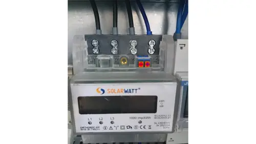
1-direction S0 meter (here: SOLARWATT EnergyMeter)
Device search in SmartSetup
Ensure that the energy storage system, inverter and SOLARWATT Manager are in the same network and are configured correctly.
- Starting the SmartSetup
Certain device types are found and installed automatically(Automatic installation)
Other device types must be installed by selecting the device driver and specifying the IP address or host name(manual installation).
Information on the installation types can be found in the table below.
Automatic installation
If the device is correctly configured and available in the network, it is displayed in green in the device list.
- If necessary, connect additional devices
- Continue with SmartSetup PV systems
Manual installation
- Select Select devices in the drop-down menu or search for the corresponding entry according to the table below.
- Enter the required specifications according to the table below:
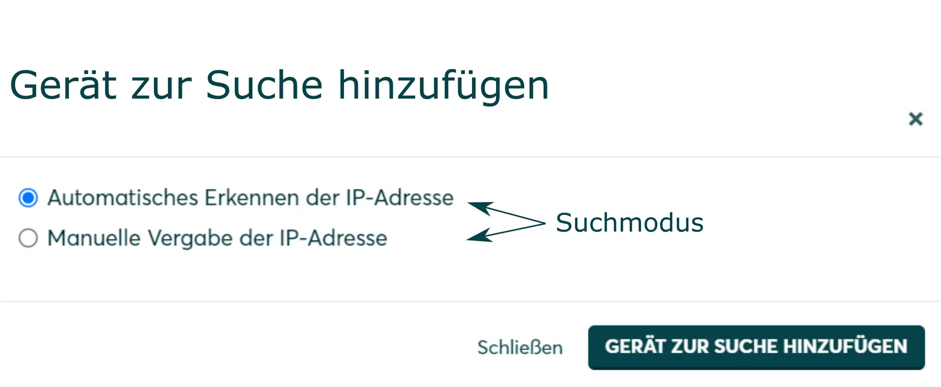
- Search mode
- iP address or host name, if applicable
- Click Add device to search.
- If necessary, add further devices to the search.
- Once you have added all the devices to be searched for, click Search for and install devices.
You can recognize correctly installed devices by the message: Device is installed. in the device list. The list also shows the current creation data.
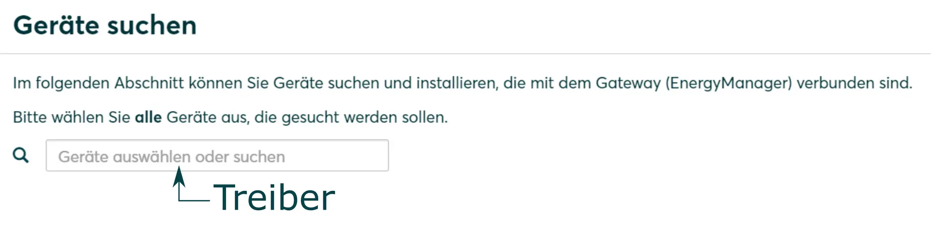
Driver selection for device search
| energyManager pro | |||
|---|---|---|---|
| Driver | Search mode | ||
| VARTA (pulse neo/element) | Varta | Specification of the IP address* | |
| AC-Sensor | ACS-solo | Automatic | |
| S0 counter | S0 counter | Specification of the interface and the pulse rate | |
| Shelly Pro 3EM | Shelly (Allterco Robotics) | Manual start of device search without specifying IP address ** | |
*) Assignment of a static IP address (via network settings VARTA or router settings) recommended.
**) Shelly devices are found after starting the device search without specifying an IP address. If the IP address of the Shelly is changed at a later date, the connection is lost and a new device search is required. It is therefore recommended that Shelly devices are assigned an unchangeable IP address.
Further information on assigning IP addresses can be found here: Device connections via network
Selected articles: