Steca
Compatibility
| EnergyManager pro | Manager flex | Firmware | |
| StecaGrid coolcept fleX XL (4213 - 10013) | ≥ 01.14 | ||
| StecaGrid coolcept fleX (1511 - 3611)* | ≤ 2.18.345 or ≥ 3.5.61 | ||
| StecaGrid coolcept3 fleX (3213 - 6013)* | ≤ 2.18.345 or ≥ 3.5.61 | ||
| StecaGrid coolcept fleX (3011 - 5011)_2* | ≤ 2.18.345 or ≥ 3.5.61 |
*) Connection via RS 485 interface
| Full compatibility | |
| No compatibility |
You can view the installed firmware version on the inverter display under Main menu > Information > System information.
The firmware versions specified above are required for a connection between the inverter and the SOLARWATT Manager. If an update is necessary, update the device firmware before commissioning. The updates and information on the procedure can be obtained from the manufacturer.
Non-compatible inverters can be recorded using separate power meters or energy meters: Non-compatible inverters
Quick guide Steca coolcept fleX XL
- Carry out the initial commissioning according to the manufacturer's instructions.
- Integrate the inverter into the local network.
- Call up the user interface of the inverter via a browser. the IP address is shown on the inverter display.
- Make the following settings there:
| category | setting | |
|---|---|---|
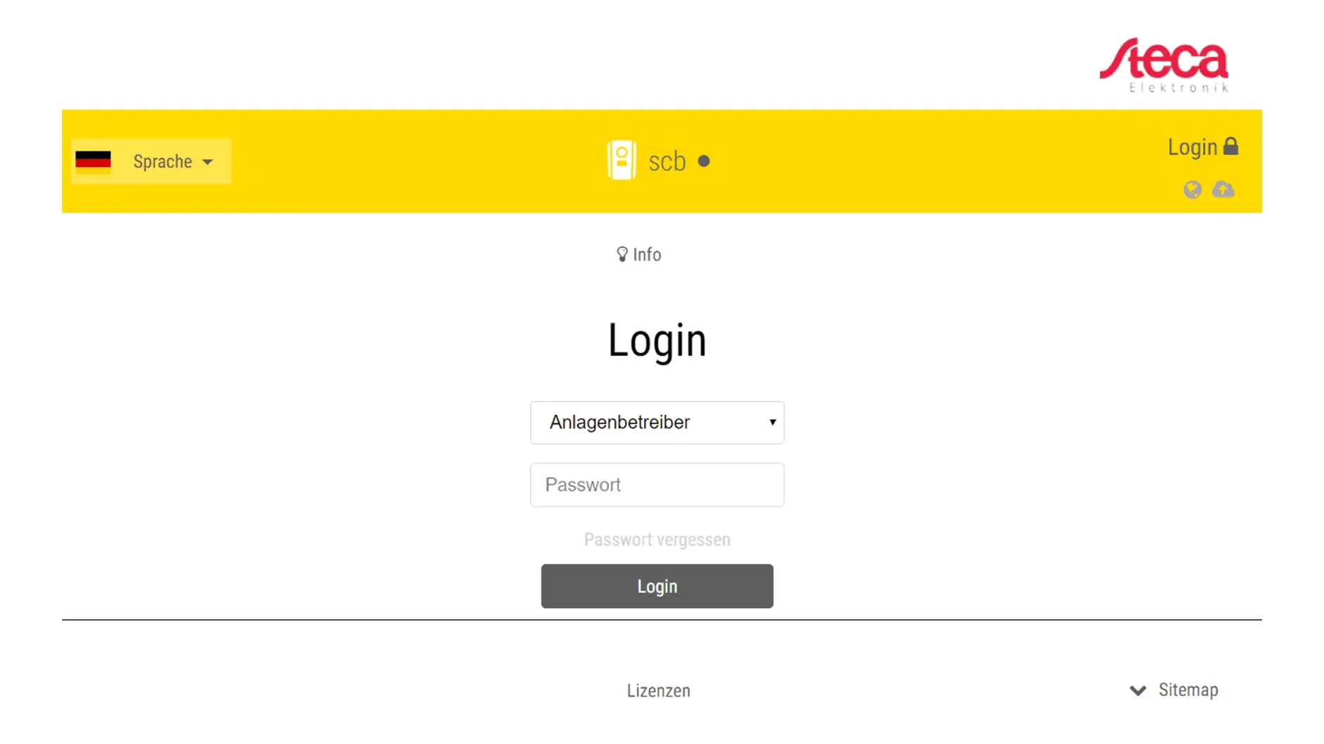
| Login as system operator | Settings > Network | assign static IP |
| Settings > Modbus / Sunspec TCP | Activate Modbus |
The assigned IP should be outside the automatic address range of the router (DHCP server).
- It may be necessary to restart the WR and the router.
Steca coolcept fleX XL configuration
- Carry out the initial commissioning according to the manufacturer's instructions.
- Integrate the inverter into the local network.
- Connect your laptop to the local network (via LAN cable or WLAN).
- Enter the IP address of the inverter in the address line of the browser. The IP address is shown alternately on the inverter display or can be queried in the inverter menu. Alternatively, you can find out the IP address via an IP scan or via the router's user interface.
Attention: a network scan requires the prior consent of your customer! - Select your preferred language and the Installer role.
- Enter your password . To log in as an installer, you will need the master key from the inverter's nameplate and your service code, which you can request from the manufacturer's service department.
- Click Login.
- Under the Settings menu item, make all the basic settings (e.g. inverter name, network settings, specifications for remuneration, log data query).
Steca inverters are not found and installed in the SmartSetup Manager using autodiscovery. The device search must be carried out by entering the IP address of the inverter. If the IP address changes during operation, the connection between the inverter and the Manager will be lost.
We therefore recommend assigning a static IP address to the WR via its network settings.
- Log out as the installer and then log in as the system operator.
The first time you log in as a system operator, you must assign a password. This is possible via Forgot password. Enter the master key and a new password in the following menu. You will find the master key on the nameplate of the inverter.
- Select the Modbus / Sunspec (TCP) submenu from the drop-down list in the Settings menu.
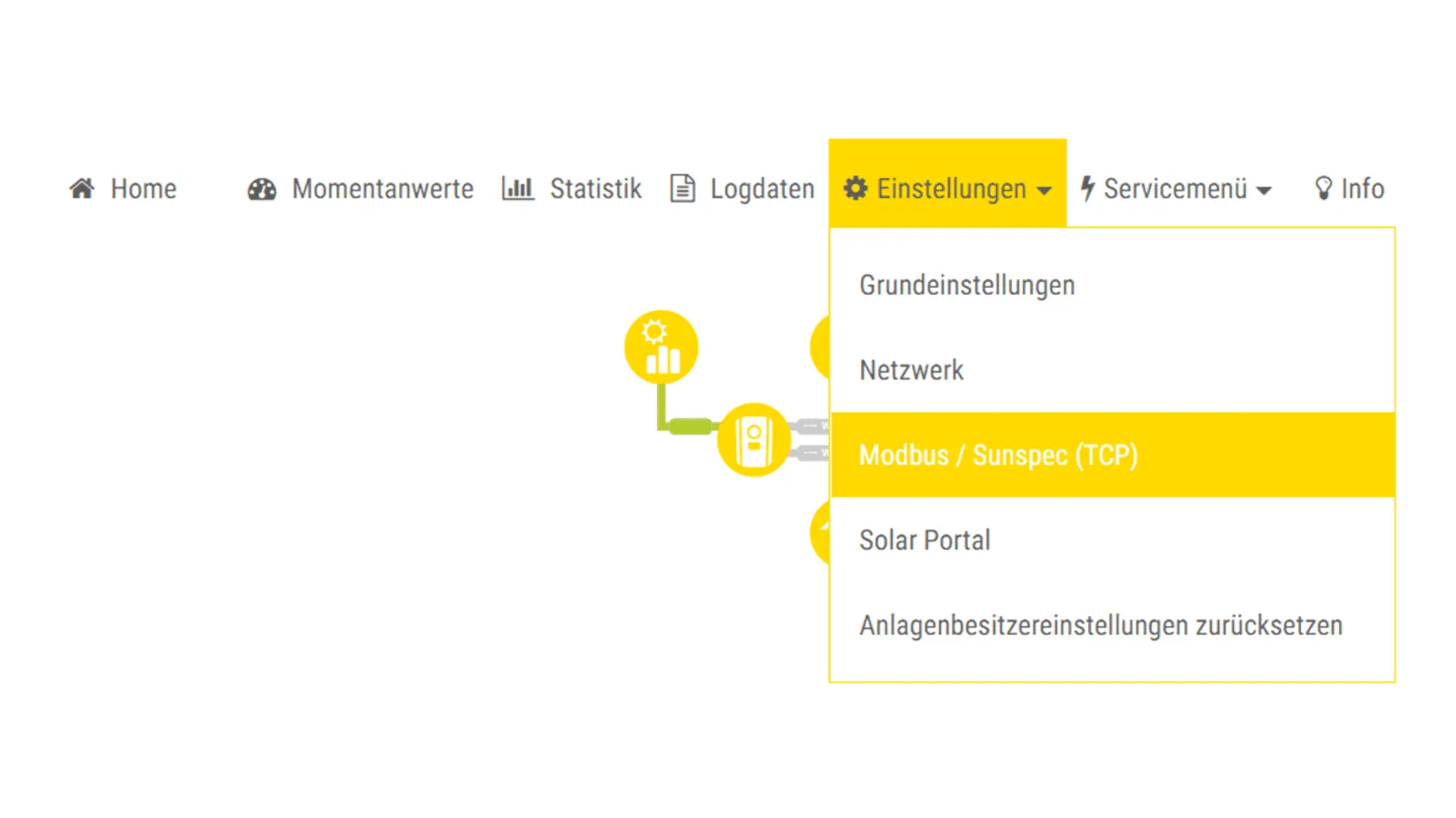
- Activate the Enable Modbus checkbox.
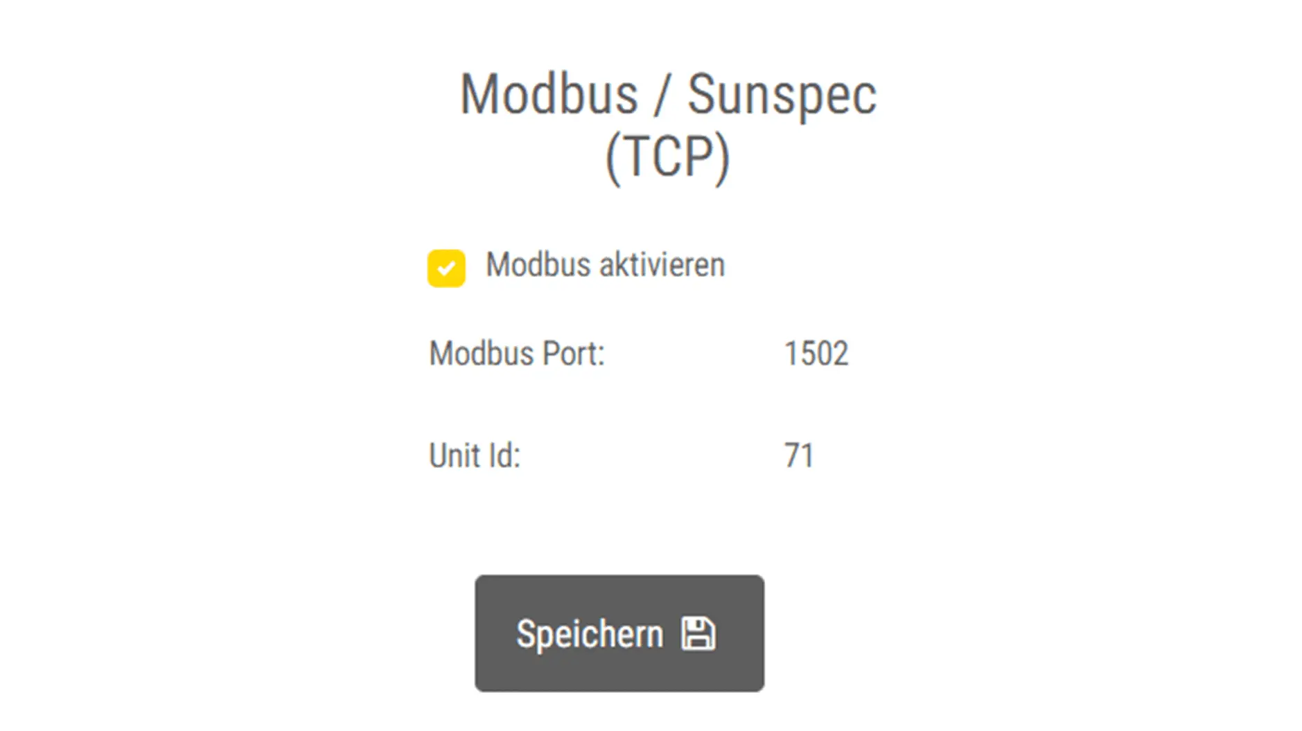
- Click Save.
- Continue with the device search in SmartSetup.
Steca coolcept / coolcept³ configuration
Ensure that the inverter is operated with suitable firmware in accordance with the table above.
The inverter only communicates when it is in operation and sufficient DC-side voltage is present. Only install the inverter when there is sufficient sunshine.
Connecting the inverter
Interface: RS485-1 / RS485-2
- Secure the work area against accidental contact with live parts.
- Install the inverter according to the manufacturer's instructions.
- Disconnect the inverter from the power supply.
- Disconnect the SOLARWATT Manager from the power supply.
- Open the inverter. Follow the manufacturer's instructions.
- Connect the inverter to the gateway as shown in the diagram
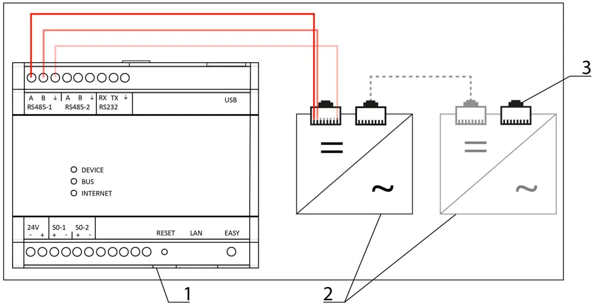
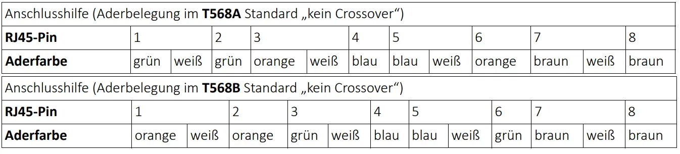
| 1 | SOLARWATT Manager | A | B | GND |
| 2 | Inverter (StecaGrid coolcept or coolcept³) | 1 | 2 | 8 |
| 3 | Termination at the last inverter | |||
Commissioning the inverter
- Connect the inverter housing properly.
- If necessary, connect other devices to the gateway.
- Secure the work area against accidental contact with live parts.
- Commission the inverter(s).
- Supply the gateway with power.
- Wait for the boot process to complete.
- Continue with the device search in SmartSetup.
Connecting several inverters
You can connect one or more inverters to the RS485-1 or RS485-2 interface.
Connect several inverters by connecting them to the free RJ45 socket of the previous inverter using a normal network cable (RJ45 plug on both sides). Only use the two RJ45 sockets on the right. Make sure to terminate the last inverter in the series. Follow the manufacturer's instructions for this.
If you connect several inverters to one RS-485 interface, make sure that the inverters are assigned different bus addresses! This configuration takes place via the manufacturer's device software. Consult your specialist partner and the manufacturer's instructions.
Only assign bus addresses in the range from 1 to 20. The gateway only searches this address range.
Error patterns and troubleshooting
No energy values are calculated for generation and total consumption:
- Check whether the firmware version installed on the device is ≤ 2.18.345 or ≥ 3.5.61.
There is no data communication:
- Check whether you have only used the right two of the three RJ45 sockets and not the LAN socket on the far left.
Device search in SmartSetup
- Starting the SmartSetup
Certain inverter models are found and installed automatically (Automatic installation).
Other inverter models are installed by selecting the device driver and specifying the IP address or host name (manual installation).
Information on the installation types of the series can be found in the table at the end of this page.
Automatic installation
If the device is correctly configured and available in the network, it is automatically displayed in green in the device list.
- If necessary, connect additional devices
- Continue with SmartSetup PV systems
Manual installation
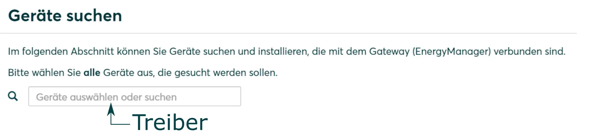
- In the Select devices drop-down menu, select or search for the corresponding driver (according to the table at the bottom of the page) for the inverter device.
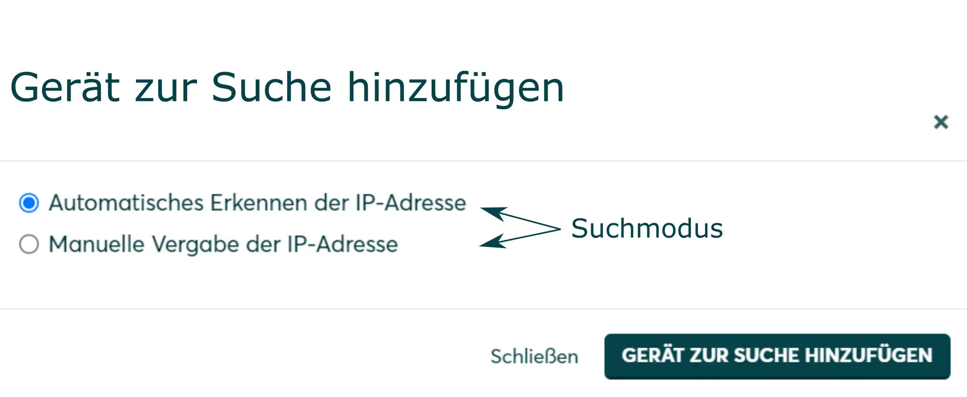
- Select the search mode (according to the table at the bottom of the page) for the WR device.
- If required, enter the IP address or host name of the device and confirm with Add device to search.
- If necessary, add further devices to the search.
- When the search list is complete, click Search and install devices.
Correctly installed devices appear in the device list with the message: Device is installed. The list also shows the current generation data.
| energyManager pro | Manager flex | ||||
|---|---|---|---|---|---|
| Driver | Search mode | Driver | Search mode | ||
| StecaGrid coolcept fleX XL (4213 - 10013) | Steca | Ethernet
| Steca SunSpec inverter |
| |
| StecaGrid coolcept fleX (1511 - 3611)* | Steca | RS485 | Model not supported | ||
| StecaGrid coolcept3 fleX (3213 - 6013)* | Steca | RS485 | Model not supported | ||
| StecaGrid coolcept fleX (3011 - 5011)_2* | Steca | RS485 | Model not supported | ||