- SOLARWATT Manager
- Commissioning
- Installation and network connection SOLARWATT Manager
Installation and network connection
Table of contents
SOLARWATT Manager flex
Installation location: outside the switch cabinet
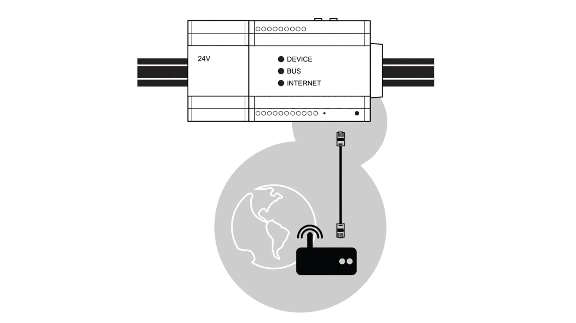
Network connection via Ethernet
Local networks usually include a router and optionally one or more switches.
- Connect the Manager to the router using the LAN cable (included in the scope of delivery).
- Connect the Manager to a power socket and wait for the boot process to complete. During the boot process, all LEDs flash several times. The boot process was successful when the status LED lights up green continuously.
- The Manager now establishes a connection to the Internet. If the process was successful, the Internet LED lights up green.
- Make sure that all devices that you want to connect are accessible in the same local network and that settings are selected that enable communication with the Manager.
Network connection via PLC
Powerline Communication (PLC) is data transmission via the domestic electric circuits. With a PLC network, the laying of network cables can be avoided.
The Manager flex can set up a Powerline network and also connect to an existing Powerline network.
To activate Powerline Communication, use the Install button on the back of the Manager flex.
Overview of PLC button functions
| Button | Actuation time | Function |
|---|---|---|
| Install | 3 sec* | Activate/deactivate PLC module ** |
| Connect | 6 sec | PLC connection mode Actuation necessary in encrypted PLC networks. |
| 1 sec | PLC key exchange Necessary in encrypted PLC networks. | |
| 10 sec | PLC reset PLC encryption is reset and connections are lost |
*) if pressed for longer, the manager may be reset
**) PLC module is deactivated at the factory. Caution: Risk of ring closure in the local network.
Practical case 1: Manager flex generates a PLC network
The Manager flex is connected to the router via Ethernet and generates a PLC network via the mains plug. This turns every socket in the house into a network socket. Other devices (e.g. inverters, battery storage systems) can be integrated into the network via additional PLC adapters.
- Connect the Manager to the router using the LAN cable (included in the scope of delivery).
- Connect the Manager to a power socket and wait for the boot process to complete. During the boot process, all LEDs flash several times. The boot process was successful when the status LED lights up green continuously.
- The Manager now establishes a connection to the Internet. If the process was successful, the Internet LED lights up green.
- Activate the PLC module. To do this, press the Install button on the back of the Manager for 3 seconds. The Connection LED on the front of the manager flashes once per second.
- Plug a PLC adapter into a socket near the device that is to be integrated into the PLC network and connect the device and PLC adapter via LAN cable.
- If the PLC network is not encrypted (depends on the settings of the PLC adapter used), the PLC connection is established automatically. If the connection is successful, the connection LED flashes every 10 seconds.
If no PLC connection could be established, the PLC adapter used expects an encrypted connection. Then proceed as follows:
- Press the button for adding new devices on the PLC adapter (pairing mode: is usually indicated by flashing LEDs). Observe the conditions instructions for the PLC adapter.
- Press the Connection button on the back of the manager for 6 seconds.
- Press the Connection button again for 1 second. A red LED behind this button then starts to flash. The connection with the PLC adapter is now established.
- If the connection is successful, the connection LED flashes every 10 seconds.
Practical case 2: The Manager flex uses an existing PLC network
A Powerline network already exists. The Manager flex can be connected to any power socket and establish a connection to the network subscribers and the Internet. No PLC adapter is required.
- Make sure that the PLC network is available and that there is an Internet connection.
- Connect the Manager to the desired socket.
- Activate the PLC module. To do this, press the Install button on the back of the manager for 3 seconds. The Connection LED on the front of the manager flashes once per second.
- Press the button to add new devices to the PLC adapter (pairing mode: usually indicated by flashing LEDs). Observe the conditions instructions of the PLC adapter.
- Press the Connection button on the back of the manager for 6 seconds.
- Press the Connection button again for 1 second. A red LED behind this button then starts to flash. The connection with the PLC adapter is now established.
- If the connection is successful, the connection LED flashes every 10 seconds.
PLC practical case 3: The Manager flex itself offers all PLC adapter functions
First proceed as in PLC practical case 2. Once the Manager flex has successfully established an Internet connection via PLC, you can connect any network-compatible device to the LAN port of the Manager. Several devices can be connected via a switch.
Further commissioning steps
Connecting devices
Installing devices on the SOLARWATT Manager
SmartSetup
Configuration according to the house installation.
EnergyManager pro
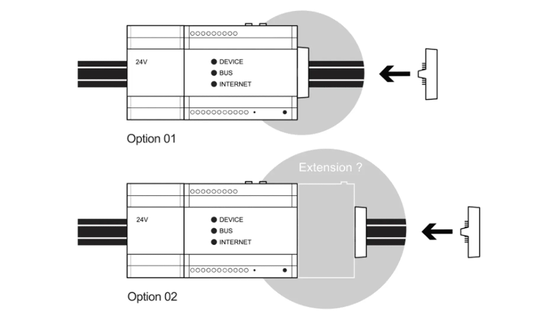
Installation location: Switch cabinet
- Remove the power supply unit and EnergyManager from the packaging.
- Remove the battery pennant.
- Mount both devices on the top-hat rail. Mount the devices as close as possible to the energy systems to which you want to connect them.
- Connect the extension bus termination plug (included in the scope of delivery) to the right of the EnergyManager (or to the right of the last digital extension, if applicable)
- connect all other energy systems (inverters, meters, etc.) to the EnergyManager
- Connect the network cable with connection to the Internet router
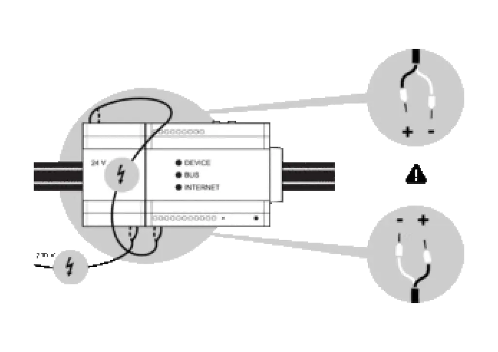
- Supply the EnergyManager with the 24 V DC voltage from the power supply unit supplied. Ensure that the polarity is correct. If the polarity is incorrect, the EnergyManager will not be supplied with power and will not switch on.
- apply 230 V voltage to the power supply unit and wait for the boot process to complete
Further commissioning steps
Connecting devices
Installing devices on the SOLARWATT Manager
SmartSetup
Configuration according to the house installation.
Selected articles: