- SOLARWATT Battery & Inverter vision
- Installation
- Inverter vision max
Inverter vision max
This page describes the assembly and wiring procedures for the SOLARWATT Inverter vision max three-phase inverter.
Install the Inverter
Please observe all safety Instructions and requirements for the installer.
Follow the specifications regarding the installation location and the maximum and minimum installation distances for the inverter, meter, and battery.
Check whether the wall’s condition and the included mounting hardware are suitable for supporting the inverter’s weight (52.5 kg).

Do not place the inverter on the terminals or on the front panel
- Mark the drill holes using the wall bracket and drill the holes (at least 50 mm deep, 8 mm in diameter)
- Install the wall bracket so that the arrow marked on it points upward
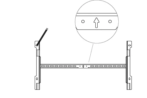
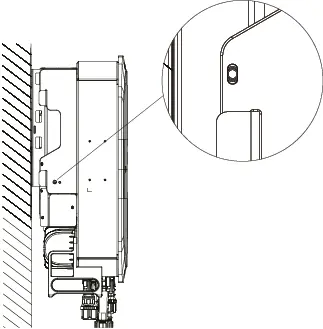
- Carefully hang the inverter on the wall bracket
- Secure the inverter to the wall bracket
Connecting the DC PV Cable
Please note the information on cable requirements for inverters, meters, and batteries.
Please note the explanations regarding crimping PV plug connectors.
The scope of delivery includes Stäubli MC4 Evo 2A PV plugs that are compatible with the Stäubli PV sockets on the inverter. Stäubli PV plugs are compatible with other types of Stäubli MC4 plugs.
- Strip the DC PV cable to a length of 6.0–7.5 mm
. Be careful not to damage any individual wires! - Crimp the DC cable to the PV plug connectors
Ensure correct polarity when assigning the PV pin contacts!

- Connect the DC PV cable to PV+ and PV- respectively
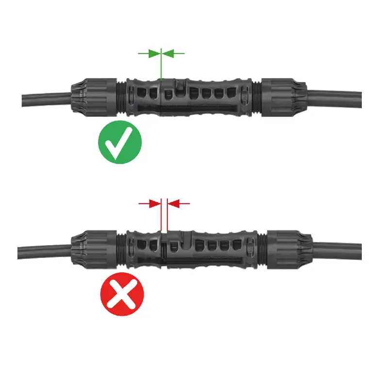
You should hear a "click."
- Check that the plug connectors are properly engaged by pulling on them
(Maximum force: 20 N)
Connect the DC Battery Cable
The DC battery cable is included in the scope of delivery for the Battery vision top pack.
- Connect the plugs (if present on both battery towers) to BAT+ and BAT-
You should hear a "click."
Install the bluetooth antenna
The antenna is included in the scope of delivery for the Inverter vision three.
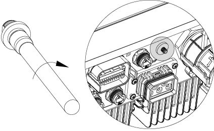
- Remove the protective rubber sleeve from the antenna connector
- Screw on the antenna
Connecting the BMS Cable
The BMS cable is a standard network cable (included in the scope of delivery for the Battery vision top pack).
- Connect the communication cable(s) (if there are two battery towers) to the BMS output
- To protect the connections in damp locations and outdoor installations, use the connector housings included in the scope of delivery for the inverter.
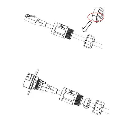
Slide the gasket over the cable and secure all components of the connector housing
Note: When using a run cable, even custom-assembled connectors may not fit through the connector housings. In that case, make sure that the connectors used are suitable for outdoor use—that is, UV- and weather-resistant—and that they meet the required IP65 IP rating.
Connect to the LAN
The Inverter vision max is connected directly to the router via a LAN connection. The LAN cable is not included in the scope of delivery.
Please note the requirements for the cable type used for the communication connection under Required Accessories and Tools.
- To protect the connection in damp locations and outdoor installations, use the connector housings included in the scope of delivery for the inverter on the inverter side
Slide the gasket over the cable and secure all components of the connector housing
Note: When using a run cable, even custom-assembled connectors may not fit through the connector housings. In this case, make sure that the connectors used are suitable for outdoor use—i.e., UV- and weather-resistant—and that they meet the required IP65 IP rating.
- Connecting the Inverter to the Router
In exceptional cases, a Wi-Fi connection can be established to connect wirelessly to a Wi-Fi network in the vicinity of the inverter.
- Ensure that the antenna is screwed onto the inverter
- Use the Solarwatt Pro app to configure the Wi-Fi settings
Further explanations regarding connecting the inverter to the local network via Wi-Fi.
Connect the communication cable to the meter
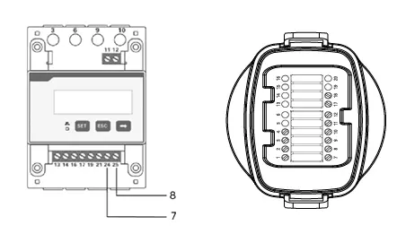
- Configure the adapter for connection to the meter (the meter adapter is included in the scope of delivery for the Inverter vision max) and connect it to the inverter
Note the requirements for the cable type used for the communication connection under Required Accessories and Tools.
The connection for communication with the DDSU meter is made via direct connections 24 and 25.
| Pin on the meter | 24 | 25 |
| Pin on the meter adapter | 7 | 8 |
Connect the AC-BACKUP
The Inverter vision max is designed for operation on a three-phase power grid, with a voltage range of 220/230/240 V and a frequency of 50/60 Hz.
Other technical requirements must comply with the requirements of the local public power grid.
Please note the specifications regarding cable requirements for the inverter, meter, and battery.
The AC-BACKUP connector is included in the scope of delivery for the Inverter vision max.
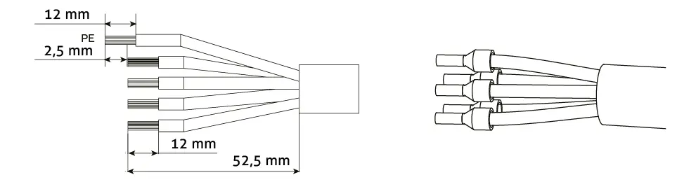
- Strip 52.5 mm of insulation from the AC cable
- Trim the N and L conductors by 9 mm so that the PE conductor can always establish a connection last
- Strip 12 mm of insulation from the PE, N, and L conductors
- Crimp the wire end ferrules
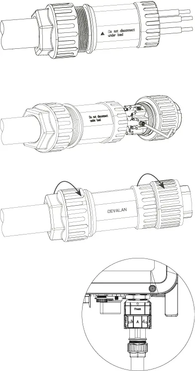
- Feed the cables through the connector
- Insert the copper wires into the connector terminals and tighten the screws
- Tighten the housing and lock nut, then connect the plug
If the connector needs to be opened again, use the unlocking tool provided
Connect AC-GRID
The Inverter vision max is designed for operation on a three-phase power grid, with a voltage range of 220/230/240 V and a frequency of 50/60 Hz.
Other technical requirements must comply with the requirements of the local public power grid.
Please note the specifications regarding cable requirements for the inverter, meter, and battery.
The AC-GRID plug is included in the scope of delivery for the Inverter vision max.
- Strip 52.5 mm of insulation from the AC cable
- Trim the N and L conductors by 9 mm so that the PE conductor can always establish a connection last
- Strip 12 mm of insulation from the PE, N, and L conductors
- Crimp the wire end ferrules
- Disassemble the connector
- Connect the cable ends to the connector according to the wire markings
- Feed the cables through the connector components
- Reassemble the connector and plug it in
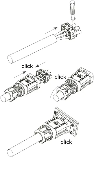
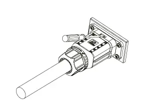
If the connector needs to be opened again, use a screwdriver to align the release position.
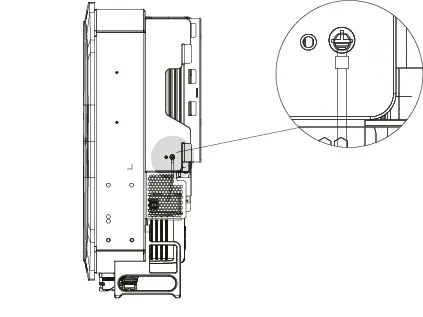
Connect the grounding wire
The ground wire is not included in the scope of delivery. The cable lug for the ground wire is included in the scope of delivery for the Inverter vision max.
Install a power limiter
Power Limitation via the Digital Connection Between the CLS Control Box and the SOLARWATT Manager
You can find detailed instructions here.
Power Limitation via Relay Contacts
- via remote control of the feed-in-power using a radio frequency remote control receiver
- Connect the data cable to the inverter's communication output
Next steps:
Continue with the Commissioning of the Inverter vision three/max
Continue with commissioning as a controllable load
Connection to the radio remote control receiver
- Connect the data cable to the inverter's communication output
- Connect the wires of the data cable coming from the inverter to the terminals of the radio-controlled receiver
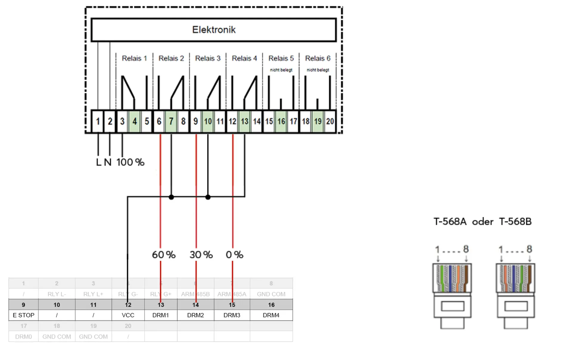
Pin Assignment for the Inverter Communication Output and Radio Remote Control Receiver
Next steps:
Continue with the Commissioning the Inverter vision three/max
Continue with the wireless radio control receiver