Panel vision M
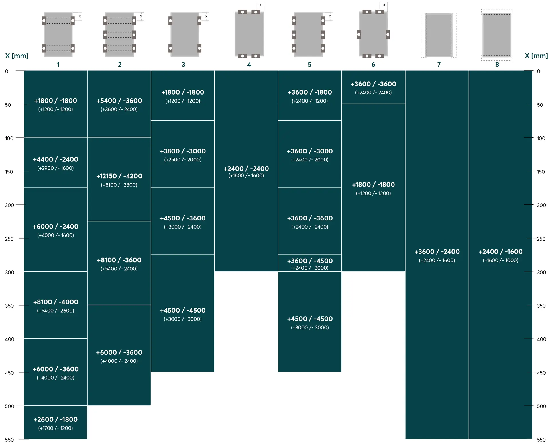
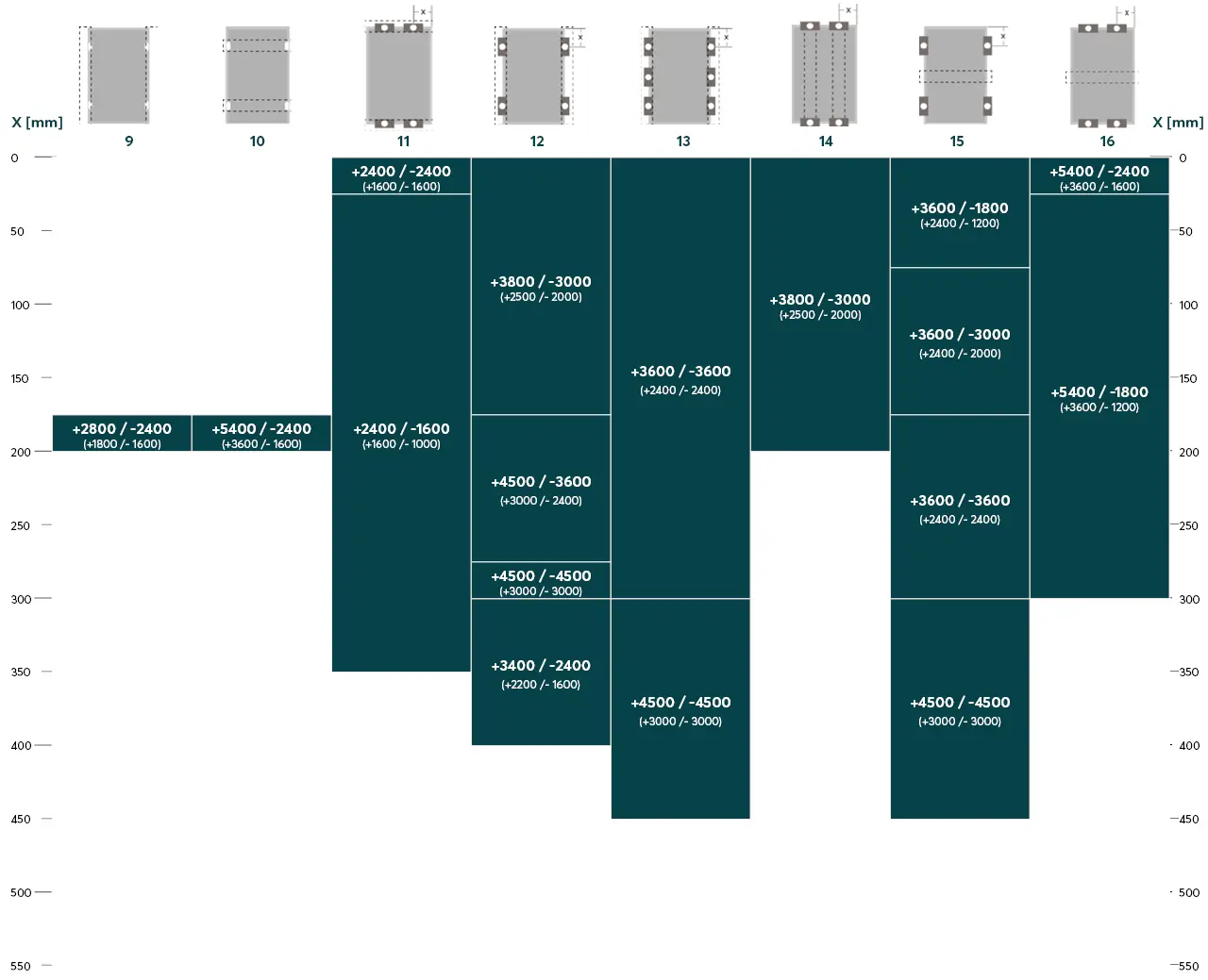
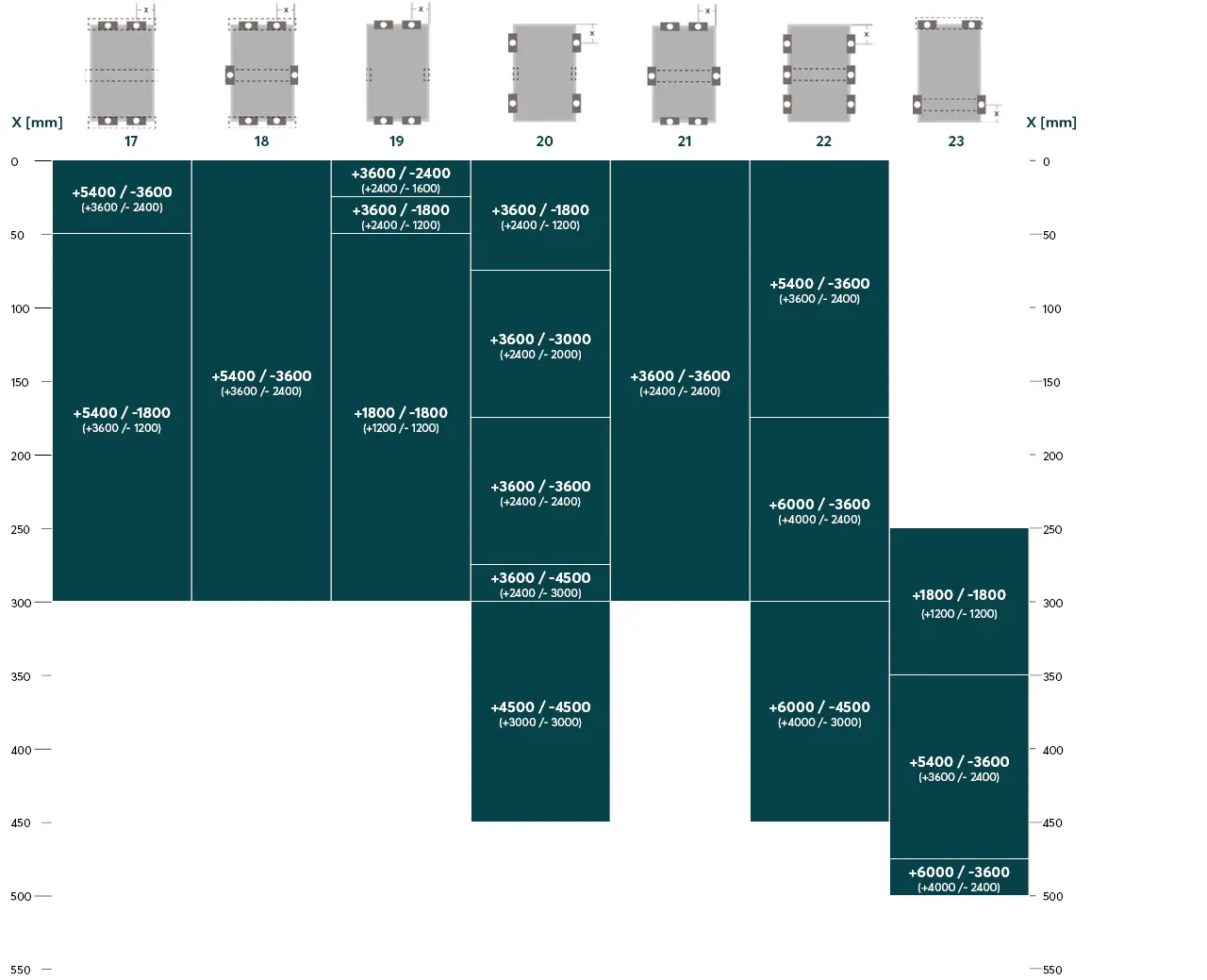
For Panel vision M (except Panel vision M construct), this page describes the type of fastening with screws, clamps or insertion system for each mounting variant, the areas on the module frame approved for fastening and the maximum permissible pressure and suction load on the module. The definition of the clamping area (x) results from the distance between the outer edge of the module and the center of the clamp used
| Variant | Number of clamps | Number of support struts |
|---|---|---|
1 | 4, long module side | 2 |
2 | 6, long module side | 3 1) |
3 | 4, long module side | - |
4 | 4, short module side | - |
5 | 6, long module side | - |
6 | 6, short module side | - |
7 | - | Insertion system |
8 | - | Insertion system |
- There must be no contact between the junction boxes and the middle support strut.
Therefore, mount the support strut with an offset to the center of the module of at least 50 to max. 100 mm.
| Variant | Number of clamps | Number of support struts |
|---|---|---|
9 | Mounting holes on the module | 2 |
10 | Mounting holes on the module | 2 |
11 | 4, short module side | 2 |
12 | 4, long module side | 2 |
13 | 6, long module side | 2 |
14 | 4, short module side | 2 |
15 | 4, long module side | 1 1) |
16 | 4, short module side | 1 1) |
- There must be no contact between the junction boxes and the middle support strut.
Therefore, mount the support strut with an offset to the center of the module of at least 50 to max. 100 mm.
| Variant | Number of clamps | Number of support struts |
|---|---|---|
17 | 4, short module side | 3 1) |
18 | 6, short module side | 1 1) |
19 | 4, short module side | selective 2) |
20 | 4, long module side | selective 2) |
21 | 6, short module side | 1 1) |
22 | 6, long module side | 1 1) |
23 3) | 4, long module side | 2 |
- There must be no contact between the junction boxes and the central support strut.
Therefore, mount the support strut with an offset to the center of the module of at least 50 to max. 100 mm. - Two punctual, central supports against pressure loads (minimum contact surface: 10 x 50 mm)
- Position the clamping points on the short side of the frame as far out as possible


